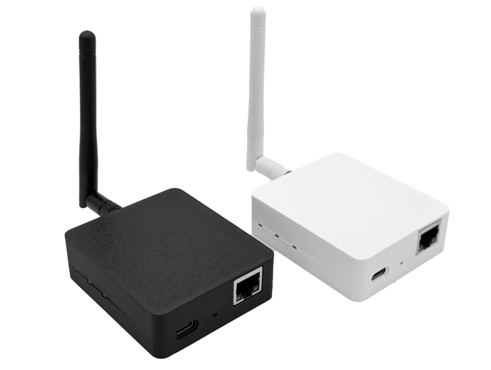
cod.m ZigBee Coordinator 1.2 (CZC-1.2)#
- Current Version V1.2
- Buy the cod.m ZigBee Coordinator
- Installation
- Firmware Download
- Z-Stack Firmware Download
- Tutorials
- FAQ
Features#
- CC2652P7 Texas Instruments multiprotocol 2.4GHz radio module
- ZigBee 3.x, Z-Stack firmware (Koenkk)
- Compatible with zigbee2mqtt (z2m), Home Assistant (zha), ioBroker, etc.
- LAN, Wi-Fi or USB mode
- PoE (802.3af) or USB-C power, <1W power consumption
- ESP32 open source firmware (cod.m UZG Fork)
- ZigBee firmware update via network and in future via web interface
- ESP32 firmware update via web interface or USB-C (Auto-BSL)
- 3D-printed case (desktop/wallmount) (CC-BY-NC-SA)
- External antenna
- Made in Germany
- CE, RoHS, WEEE
Installation#
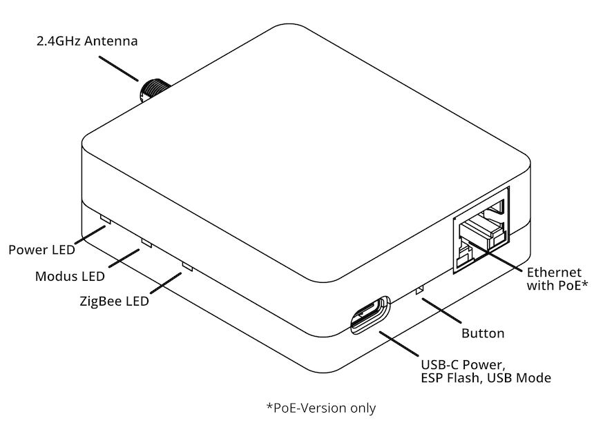
- Screw the supplied antenna onto the antenna socket.
- Connect the cod.m ZigBee Coordinator to Ethernet and/or USB-C power supply. When using Power over Ethernet*, the USB power supply unit is not required.
- The red and green LED on the coordinator light up at startup. When only the green LED is lit, the coordinator is ready for operation.
- Get the DHCP IP from your router and access it via the browser:
http://192.168.xx.xx/or use mDNS athttp://czc-xxxx.local. - No further configuration is required for operation. However, individual settings and operating modes can of course be set in the web interface.
- Continue the setup according to the automation used:
* only in PoE version
LAN/Wi-Fi#
The web interface can be used to change the usual Ethernet settings or configure the use of WLAN. In this case, power can be supplied via PoE or USB.
Warning
We strongly advise against using Wi-Fi in ZigBee operation. Serial communication over Wi-Fi is not robust enough and does not contain any error correction mechanisms to compensate for fluctuating connections or packet loss. The same applies to WAN and VPN connections.
See also zigbee2mqtt: Connect to a remote adapter and HomeAssistant: Zigbee Coordinator over Wi-Fi/WAN/VPN.
When used as a Thread Border Router (currently under development), this problem does not occur.
USB mode#
The cod.m ZigBee Coordinator can be switched to USB mode by briefly pressing the button once. This allows the coordinator to be used directly via USB on the desired host application. See also the Push-button section in these instructions.
Power supply#
The power consumption in PoE mode is ~0.9W, in USB mode ~0.7W.
Power over Ethernet (PoE)#
Power over Ethernet (PoE) 802.3af is only available in the PoE version. USB-C power supply naturally also works with the PoE version. USB-C can be plugged into this PoE version at any time without interruption. When switching from USB-C to PoE power supply, the coordinator restarts, as the PoE interface chip must first negotiate the voltage with the PoE switch.
USB-C#
A USB-C power supply with 5V and minimum 400mA is required. A suitable power supply can be purchased in the cod.m shop: goobay USB-C Charger Set 45298.
LEDs#
The coordinator has three LEDs that indicate the operating status. The LEDs can be controlled separately under the General menu item.

Power LED (green)#
Indicates existing power. The power LED can be controlled and deactivated separately via software. As of CZC Firmware Version 2.0 the LED blinks (1x per second) until a connection from the hostapplikation is made.
Mode LED (red)#
The red LED lights up when USB mode is switched on. The mode LED can be controlled and deactivated separately via software. With firmware version 2.0 the mode LED has additional functions:
- blinking: Active during Zigbee chip connection check at startup (normally not visible)
- constant: USB mode active
- off: Network mode active
- blinking fast: Communication error with ZigBee chip (3x per second)
ZigBee LED (yellow)#
This LED is directly connected to the ZigBee module (CC2652P7) and lights up when pairing is switched on, for example. The ZigBee LED can be controlled separately via software.
/V1.2
Push-button#
Firmware V2.0 and up#
Factory settings#
To reset the Coordinator to factory settings, disconnect the Coordinator from the power supply. Then hold the button on the device for >10 seconds while reconnecting the power supply.
- Disconnect the power supply/PoE
- Hold the button
- Connect power to the coordinator, PoE will also work
- Release the button
- Wait for the Coordinator to boot up again
Other actions#
- Short press (less than 3s): LED on/off, not persistent
- Long press (3-5s): Toggle between USB and network mode
- Longer press (more than 5s): Activate ZigBee module bootloader
Firmwarwe V1.0#
Various actions can be carried out on the coordinator via the push-button. The easiest way to press the button is with a bent paper clip (or similar).
- Short press: Activate/deactivate USB mode. Indicated by the illuminated mode LED (red).
- Hold for 2-4 seconds: LEDs on/off
- Hold for 4-8 seconds: Activate ZigBee module bootloader
- Hold >10 seconds: Coordinator factory reset
Links#
- cod.m ZigBee Coordinator at the cod.m Webshop
- Der lange Weg zum cod.m ZigBee Coordinator - allgeek TechBlog [DE]