WLED Auto OFF#
- Current Version: V1.0 (Art. No. 90068)
- Automatic, signal-based load disconnection for addressable LED strips
- Standalone board – can be used with any WLED controller
- Buy cod.m WLED Auto OFF
- Instructions and connection diagrams
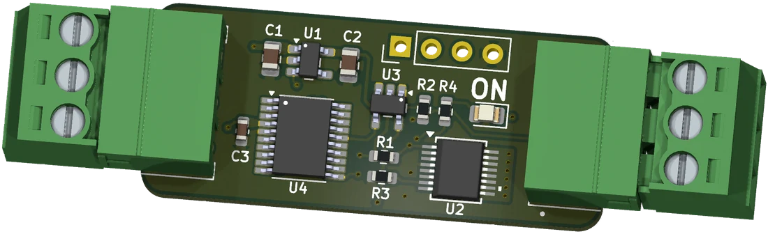
Features#
- Automatically switches the power supply of an addressable LED strip on and off based on signal activity
- Monitors the data signal (WS281x, SK681x, etc.) between the WLED output and the LED strip
- Disconnects the strip's supply voltage once no active LED data has been present for 5 seconds
- Automatically restores the supply within approx. 50ms as soon as data activity resumes
- The data signal is passed straight through, WLED operation is not affected
- No configuration in WLED, no spare GPIO and no control wire required
- Suitable for 5V, 12V and 24V installations, up to 10A load current
- Electronic high-side switch, no mechanical relay
- Status LED indicates the switching state of the output voltage
- Made in Germany, CE, RoHS, WEEE
Basics#
Digital LED strips draw current even when all LEDs are set to "off". Every chip (WS2812B, WS2815, SK6812, etc.) stays powered and waits for new data.
How much this adds up to depends on LED density, chip type and operating voltage, and varies accordingly – as an order of magnitude roughly 0.1 to 1.6W per metre. Depending on the type, a 5m strip can therefore draw up to around 8W permanently without producing any light. Over a year that is about 70kWh.
For your own installation there is no substitute for measuring: switch all LEDs off, measure the current at the injection point and multiply it by the operating voltage.
On top of that, the LED power supply stays under a permanent low load and therefore operates in an inefficient range.
The WLED Auto OFF therefore physically disconnects the LED strip supply voltage as soon as WLED stops its output, and restores it as soon as data is present again. The controller itself remains powered and reachable over the network at all times.
How it works#
The module is inserted into the line between a WLED output (data and power) and the connected LED strip. A microcontroller on the module continuously monitors the data signal:
- Active LED data → strip supply switched on
- No active LED data for 5 seconds (LEDs off / no signal change) → an internal solid-state high-side switch fully disconnects the supply voltage
- Data activity resumes → the supply voltage is reconnected within approx. 50ms, before the data is forwarded to the strip
There is practically no perceptible delay. The data signal itself is passed straight through and is not affected. The 5 second switch-off delay prevents short gaps in the data stream – for example while changing a preset or restarting the controller – from triggering a disconnection.
A status LED (ON) on the board indicates the current switching state of the output voltage.
Info
The WLED controller itself is not switched off by the WLED Auto OFF. It stays in operation so that WLED remains reachable via network, MQTT or your automation system and can switch the load back on at any time.
Wiring#
The module has one three-pole screw terminal each for input and output. Input and output are marked with an arrow on the silkscreen of the board.
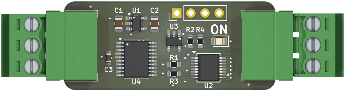
- Input: data and supply voltage from the WLED output or from the WLED Range Extender OUT module (Art. No. 90066)
- Output: switched supply voltage plus the data signal, passed straight through, to the LED strip
Terminal assignment#
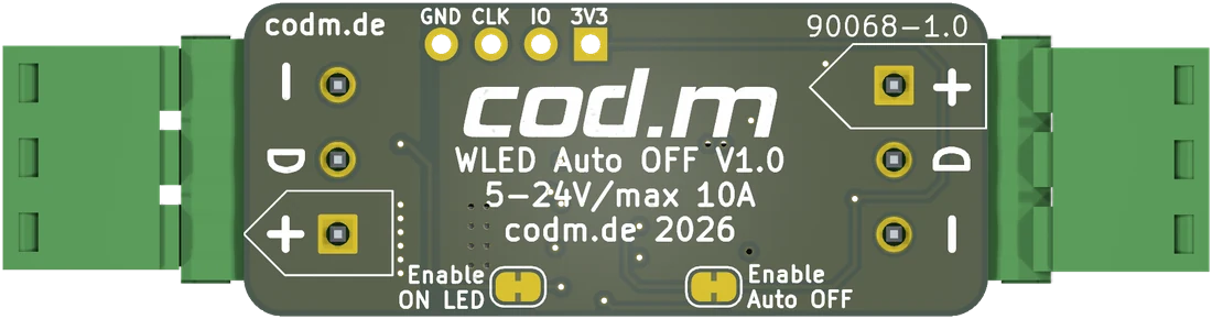
The assignment is mirrored at the two ends. On the back of the board every terminal is individually labelled + (5–24V), D (data) and - (GND), and the arrow indicates the flow direction – if in doubt, the labelling on the board applies.
| Position | Input | Output |
|---|---|---|
| top | 5–24V | GND |
| middle | Data | Data |
| bottom | GND | 5–24V |
Positions refer to the top view with the input on the left and the output on the right. Because of the mirrored layout, the output follows the same order as the pads of an LED strip (GND, Data, 5V) – the three wires therefore run to the strip without crossing.
Commission the module in the following order:
- Disconnect the installation from power.
- Wire the module between the WLED output and the LED strip according to the wiring diagram, observing the arrow direction.
- Make sure the cable cross-section matches the power draw of the connected LED strip.
- Switch on the power supply. The module requires no configuration and is ready to use immediately.
While LED data is active the strip supply stays switched on; after 5 seconds without LED data it is disconnected automatically. The status LED indicates the current switching state.
Caution
When feeding power into the LED strip at multiple points, every injection point must be located downstream of a WLED Auto OFF – see Multiple power injection.
Solder jumpers#
There are two solder jumpers on the back of the board. Both are closed on delivery – the module is ready to use without any modification. To open one, cut the bridge between the two pads with a sharp knife; to close it again, bridge the pads with solder.
| Solder jumper | Closed (as delivered) | Open |
|---|---|---|
Enable Auto OFF |
Automatic switch-off active | Automatic switch-off disabled, output permanently on |
Enable ON LED |
Status LED indicates the switching state | Status LED permanently off |
Opening Enable ON LED only changes the indication, not the function – useful if the LED is distracting at the installation site.
Info
With Enable Auto OFF open, the module acts as a pass-through: the LED strip supply stays switched on permanently and the status LED stays dark. This is useful during troubleshooting to temporarily rule out the switch-off as a cause.
The four pads GND, CLK, IO and 3V3 next to them are the programming interface for the firmware. They are used during production and have no function in operation.
Sizing#
The module is rated for up to 10A load current. How many LEDs can be switched with it follows from the maximum power of the LED strip used and the power supply dimensioned for it – the decisive figure is the manufacturer's rating of the strip in W/m or mA per LED. The brightness limiter in WLED can cap the current draw further and thus increase the number of LEDs that can be switched.
Multiple power injection#
If the LED strip can draw more than 10A, a single power injection is not sufficient. As a rule of thumb, power should be injected every 2.5m at 5V, every 5m at 12V and every 10m at 24V anyway. The strip is then split into sections that are supplied at several points.
Caution
Every additional injection point requires its own WLED Auto OFF. If a section is fed directly from the power supply, that part of the strip stays powered permanently – the disconnection then only applies to the section behind the first module.
Rules for the installation:
- At every injection point another WLED Auto OFF is inserted into the data and supply line. The data signal comes from the data output of the preceding strip section – so every module receives its data signal automatically.
- At the transition between two sections, only data and GND are carried over. The 5–24V line of the preceding section is not continued at this point – the following section is supplied exclusively through its own WLED Auto OFF.
- The current draw of each supplied section must not exceed 10A – otherwise split it further.
- All modules can be operated from the same power supply, provided it can deliver the sum of the currents.
For the injection points including fusing we recommend our WLED Fused Power Capacitor Board. Size the fuses according to the current draw of the respective section.
Notes#
- The module only switches the LED strip supply voltage – neither the controller supply nor the mains input of the power supply.
- The module is not suitable for analog, single-color LED strips without a data signal.
- The load output is not galvanically isolated.
- The module is intended for indoor use only (IP20). Protect it from dust, liquids, heat, direct sunlight and electrostatic discharge.
- Frames sent within the switch-on window of approx. 50ms may be lost. Since WLED keeps sending continuously, the image is correct immediately afterwards.
Technical data#
| Short name | cod.m WLED Auto Off V1.0, Art. No. 90068 |
| Supply voltage | 5–24V DC, max. 10A load current |
| Switching times | Switches off after 5s of inactivity, switches back on within approx. 50ms |
| Signal | WS281x, SK6812 and compatible, single-wire |
| Connection | Pluggable screw terminal, 3-pole per side |
| Ambient conditions | IP20, +5 to +45°C |
| Dimensions | PCB approx. 38 x 16mm |
| Weight | approx. 8.5g incl. connectors |
| Conformity | EMC 2014/30/EU, RoHS 2011/65/EU |
| Support | support@codm.de, no phone support |
Links#
- cod.m WLED Auto OFF in the cod.m Webshop
- cod.m WLED LAN Controller
- cod.m WLED Controller (Wi-Fi)
- cod.m WLED Range Extender
Instructions and connection diagrams#
- Quick Start Guide / Datasheet WLED Auto OFF V1.0
- Connection diagram WLED Auto OFF V1.0
- CE Declaration of Conformity cod.m WLED Auto OFF (German)
Versions#
V1.0#
- Art. No. 90068
- Input voltage 5–24V DC, max. 10A load current
- Signal evaluation via microcontroller, load switching via high-side switch
- Switches off after 5s of inactivity, switches back on within approx. 50ms
- Status LED for the switching state of the output voltage