cod.m WLED Range Extender#
- current version: V0.4
- Buy the cod.m WLED Range Extender
- Instructions and wiring diagrams
- Tutorials
- FAQ
Features#
- Developed to extend the data line of single-wire addressable LEDs (e.g. NeoPixel)
- Designed for the control of 5V, 12V and 24V LEDs: WS2812(B), WS2813, WS2814, WS2815, SK6812, etc.
- Integrated fuse with signalling LED and backup capacitor in the output module (fused capacitor board)
- Use between controller and LED strip or between two LED strip sections.
- Range up to 250m, theoretical maximum 1200m
- less than 0.2W power draw per pair
- +/- 15kV ESD protection
- Made in Germany, RoHS, WEEE
Operating Principle#
The cod.m WLED Range Extender converts the 800kHz signal of the WLED Controller into a signal on a differential pair (RS-485) so that the usual data line length of two metres (2m) can be exceeded. With the range extender, cable lengths of up to 250 metres are possible on a twisted pair cable (CAT cable, JY-ST-Y, ‘bell wire’). A fused capacitor board is also integrated in the WLED Range Extender OUT module. This means that only one board is required at the beginning of the LED strip. As each LED of a digital strip generates a new data signal, the range extender can also be used to extend the data signal between two LED strips. In addition, several OUT modules can be supplied with one IN module of the range extender. This allows the WLED signal to be multiplied.
Getting started / Connections#
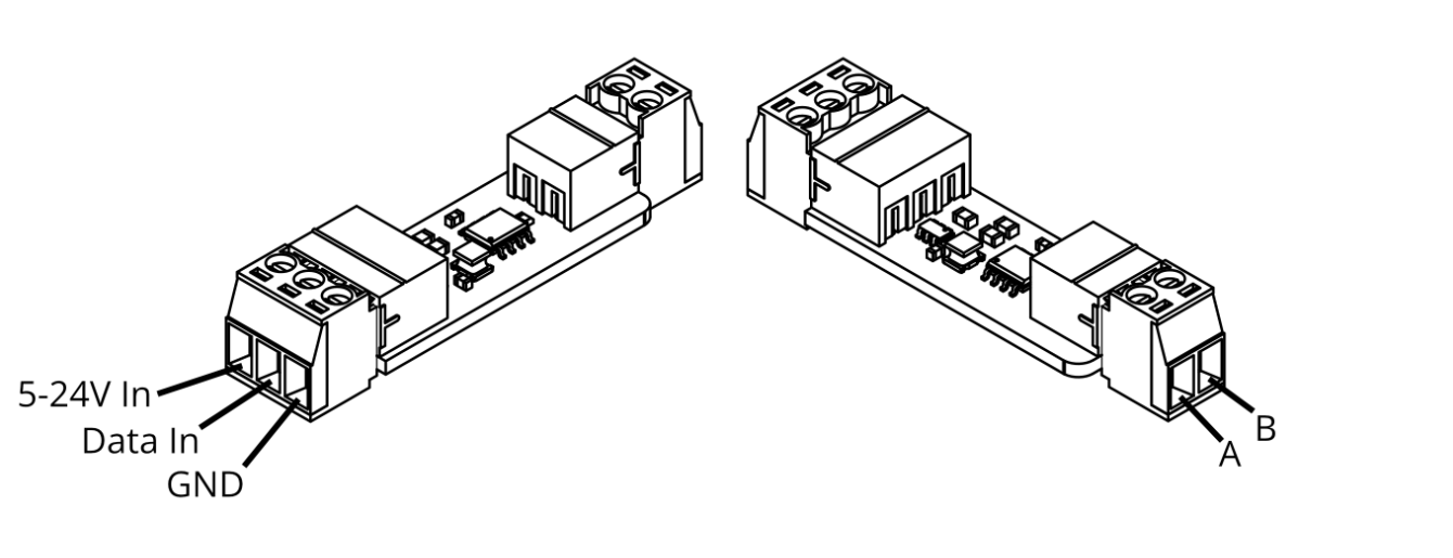
- When switched off, wire the controller and the Range Extender IN module according to the connection diagram. The IN module can be supplied with 5-24V.
- Establish the connection between the range extenders (A/B) using twisted pair (twisted wire pair). Ensure that A/B is not reversed. Ideally, connect a shield in accordance with DIN EN 60204-1; unshielded is also possible for short distances.
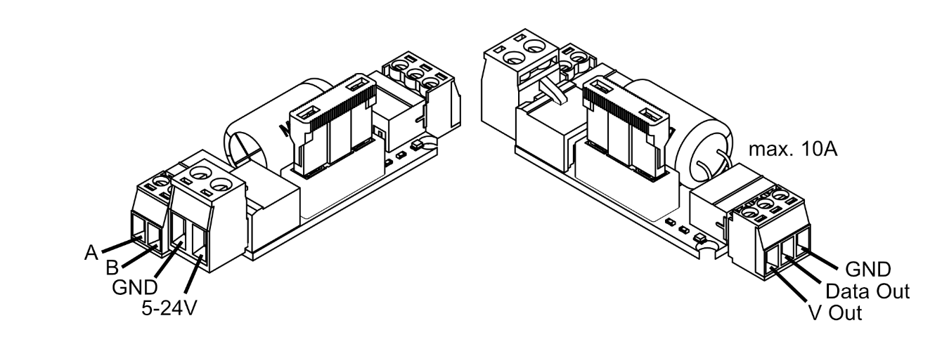
- Connect the power supply to the OUT module. Select the cable cross-section according to the power of the connected strip - load with a maximum of 10A. If there are several feeds, use additional Fused Capacitor Boards and dimension the fuses proportionally to the total power. See also the WLED Fused Capacitor Board instructions.
- Switch on the power supply, configure and use the controller according to the instructions.
- The WLED Range Extender does not require any further configuration.
JST-SM#
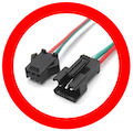
Attention!
JST-SM connectors can be loaded with a maximum of 3A. Connect additional cables or avoid JST-SM connectors completely .
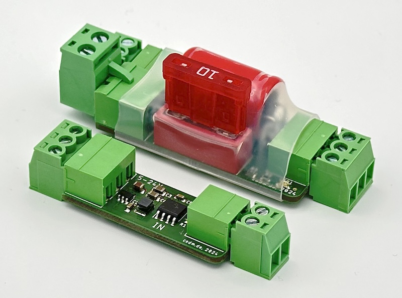
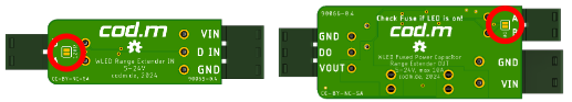
WLED Range Extender IN Module#
WLED Range Extender OUT module#
Terminating Resistors#
In difficult environments, with poor line quality or over very long distances, poor data transmission and the resulting interference at the signal output can occur. To eliminate faults, always check the twisted pair cable and, if necessary, connect the 120Ω terminating resistor to both modules using a solder jumper. This slightly increases the power consumption of the WLED Range Extender.
Instructions and connection diagrams#
V0.4#
V0.2#
- Quick Start Guide Pixel Range Extender V0.2
- Connection diagram Pixel Range Extender 5V LED Strips
- Connection diagram Pixel Range Extender 12V LED Strips