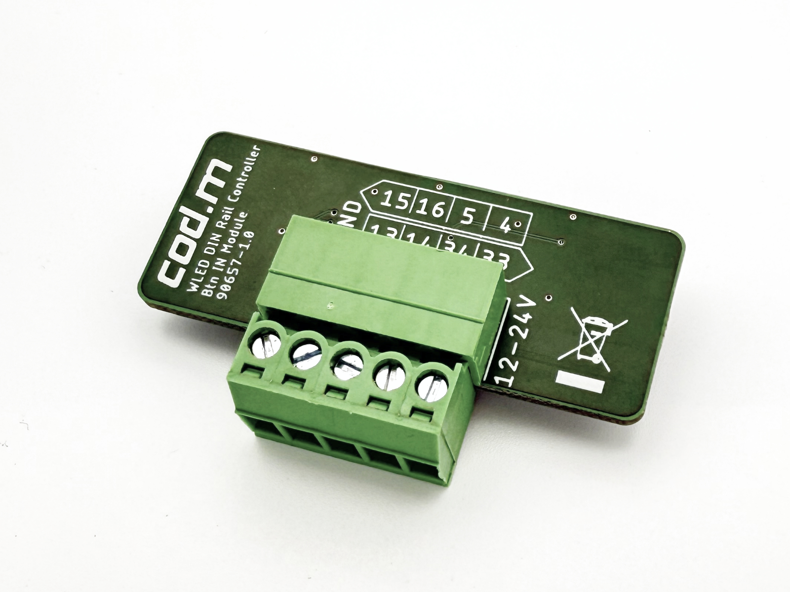
WLED LAN Controller Button IN Module#
- Current Version: V1.0
- Add-on module for the cod.m WLED LAN Controller
- Buy cod.m WLED LAN Controller Button IN Module
- Instructions and wiring diagrams
Features#
- Module for connecting up to four separate push buttons (12–14V) to trigger actions in WLED
- Galvanically isolated inputs (optocouplers)
- Add-on module for the cod.m WLED LAN Controller V1.x
- Made in Germany, RoHS, WEEE
Wiring#
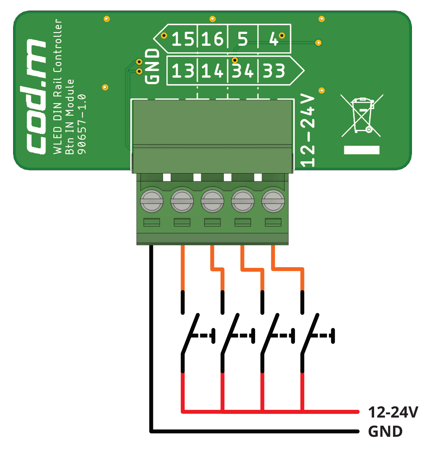
The button inputs are galvanically isolated and require their own power supply.
When powered off, connect buttons according to the wiring diagram, along with the corresponding ground.
The inputs can be used with buttons, switches, or motion detectors – these are standard potential-free contacts. For WLED, these are typically configured as Pushbutton/Push inverted or Switch.
Touch and Analog inputs are not supported.
Configuration#
Button Inputs / GPIOs#
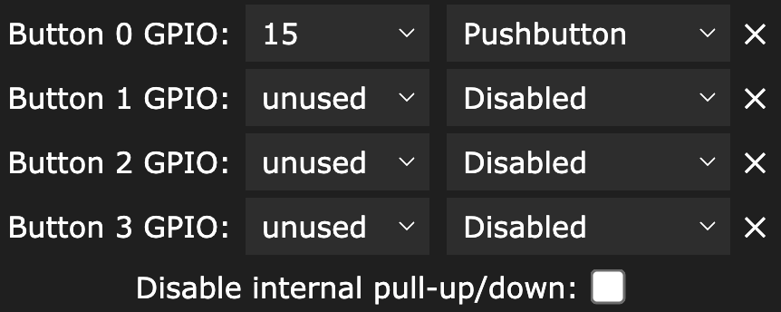
Buttons or switch inputs are initially configured in WLED under "LED Preferences" with their GPIO and type. GPIOs are labeled on the Button IN board and vary depending on the left or right module slot.
For the left module slot: 15, 16, 5, and 4
For the right module slot: 13, 14, 34, and 33
The setting "Disable internal pull-up/down" can be enabled, since the Button IN module includes its own pull-downs.
If any GPIOs appear grayed out, please check under "LED Preferences" and "Usermods" to ensure those pins aren't already in use. If they are, reassign the function to another GPIO or set it to "unused".
When changing GPIOs in the Usermods section, WLED must be restarted for changes to take effect.
Link an Action#
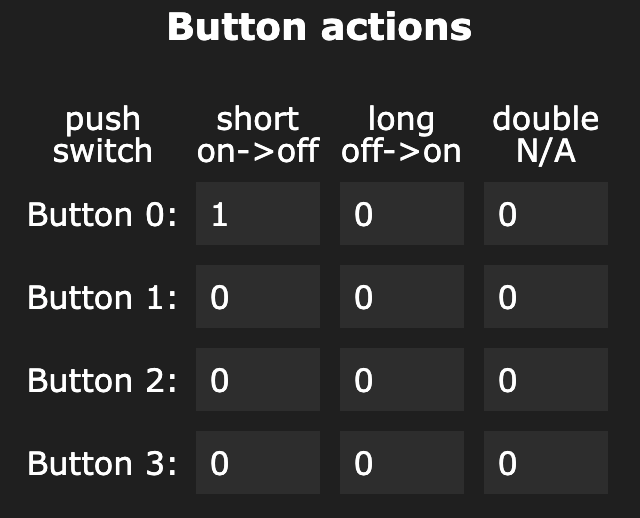
After configuring the GPIOs for up to four buttons/switches, you can assign an action to each button under "Time & Macros". An action is defined by a preset, which can be created freely on the WLED main page.
A preset consists of any configuration made through the interface or defined manually using API commands. Presets are referenced by their preset ID.
Preset Definition#
Example 1: API Command#
- Press the “+ Preset” button to create a new preset
- Name it “on/off toggle” and uncheck “Use current state”
- Enter
T=2as the API command – see https://kno.wled.ge/interfaces/http-api/ - Save the preset and note its ID
- Then go to “Time & Macros” and enter the noted preset ID for Button 0 under “short on/off”, then save
- From now on, the button on the first configured GPIO will toggle WLED on and off
You could also create a preset for “long off/on” that always turns WLED off (T=0).
Example 2: Load settings from web interface via button#
- Set up your desired configuration via the web interface
- Press the “+ Preset” button
- Give it a name
- Click “Save” and note the preset ID
- Then go to “Time & Macros” and enter the noted preset ID for Button 1 under “short on/off”, then save
- When pressing the button connected to GPIO for Button 1, the stored preset will be applied
Links#
Instructions and Wiring Diagrams#
Versions#
V1.0#
- Input voltage 12–24V
- Four galvanically isolated inputs via 2 x optocouplers LTV827S