WLED LAN Controller (PoE, DIN rail)#
- Current version: V1.2
- Buy the cod.m WLED LAN Controller
- WLED firmware download
- Instructions and wiring diagrams
- Tutorials
- FAQ
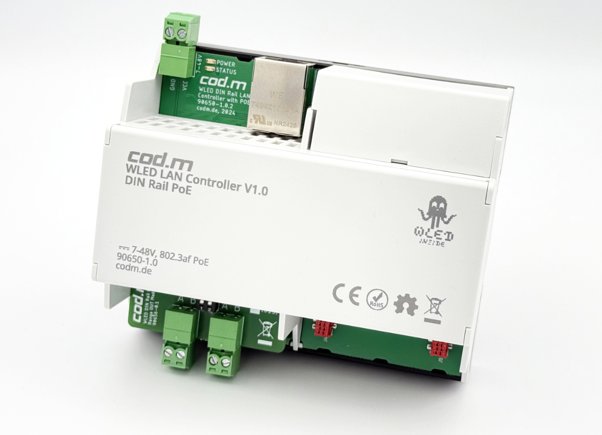
Features#
- Ready to use with WLED (Ethernet version) already installed
- LAN connection with Power over Ethernet (802.3af), fallback to WLAN
- DIN Rail Case (Phoenix Contact)
- Pluggable output modules with Range Extender OUT or Direct OUT (additional modules planned)
- Up to four lanes with 1000 LEDs each
- 12-24V DC supply voltage or PoE (802.2af)
- Reverse polarity protection
- Self-programmable if required, flash/reset button on board
- Made in Germany
- CE, RoHS, WEEE
Basics#
The cod.m WLED LAN Controller enables WLED installation in the distribution cabinet or in the sub-distribution board. With the Range Extender OUT module, the LED strips can be placed up to 250m away from the controller. Alternatively, LED strips can be operated up to two metres ditance with the Direct OUT module. The power supply for the strip (load current) is completely separate from the controller. For multiple power feeds, we recommend using our WLED Fused Power Capacitor Board. If you have multiple power feeds, ensure that the fuse is of the appropriate size.
Data signal#
The data signal of the digital LED strips (WS281x, SK6812, etc.) can normally be used safely up to two metres from the controller. Each LED regenerates the data signal, allowing a distance of two metres between the LEDs.
If the controller is installed centrally (e.g. in a sub-distribution board), it is of course not possible to install all LED strips at a distance of two metres. For this reason, we have integrated the principle of the WLED Range Extender into the WLED LAN Controller.
The basic configuration of the WLED LAN Controller includes a WLED LAN Controller Range OUT Module (item no. 90656) for plugging onto the controller and a WLED Range Extender OUT (no. 90066). Additional WLED Range Extender OUT boards and plug-in modules can be ordered separately.
Segments#
For WLED, all connected LED strips together form one logical strip. This means, for example, that an effect runs from the first to the last strip as if it were a single long strip.
If, for example, you install strip 1 in the living room and strip 2 in the hallway, WLED cannot distinguish between them at first. The solution to this is called segments: In the WLED configuration, you can define segments for parts of the strip that can be controlled separately with minimal restrictions. You can either create these segments manually, which also allows you to subdivide them, or, starting with WLED version 0.15beta, you can have a segment created automatically for each connection on the controller when configuring the strips.
Segments can be controlled as desired in the WLED web interface as well as via the interfaces.
It therefore makes sense to name the segments accordingly so that they can be easily assigned.
Warning
When using presets, the selected segments are also saved. This means that effect overlaps may occur. Please pay attention to the assignment of the segments in the presets.
Info
With the current WLED version 0.15, timing problems may occur with effects, which are noticeable by brief flickering of the individual segments. In this case, simply change the effect speed slightly.
Slots#
The WLED LAN Controller offers two slots for output or input modules.
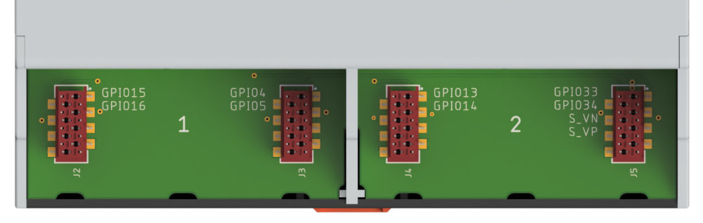
- GPIOs
15,16,4and5are available in the left slot (1). On the output module, these correspond to GPIO15and16. - GPIOs
13,14,33,34,S_VNandS_VPare available in the right slot (2). On the output module, these correspond to GPIOs13and14.
Currently available modules#
- WLED LAN Controller Range OUT Module: for connecting two LED strips via twisted pair at a maximum distance of 250 m. One Range Extender OUT module is required per strip.
- WLED LAN Controller Direct OUT Module: for connecting two LED strips at a maximum distance of 2 m
- WLED LAN Controller Button IN Module: for connecting four buttons (12-24V, galvanically isolated).
Further modules are planned for the future.
Connections / GPIOs#
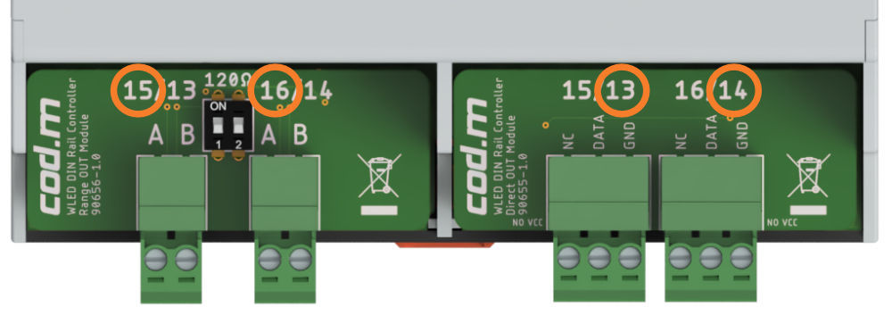
Depending on whether an output module (OUT module) is plugged in on the left side (1) or the right side (2), different GPIO must be configured. The pins used by the module are documented on the circuit board. The logic is highlighted again in the image above.
The LED strips are connected according to the connection diagram depending on the module used.
When connecting the Range OUT module, please always follow the instructions in the WLED Range Extender.
Configuration#
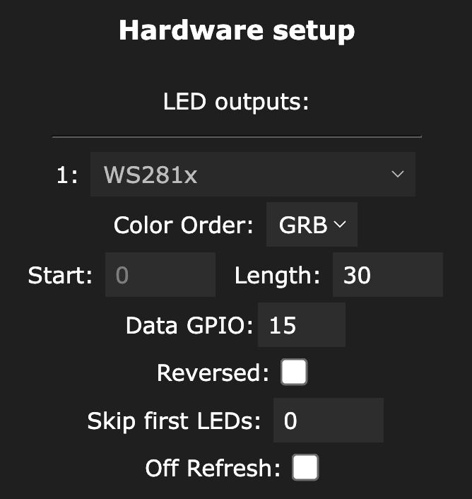
Under LED Preferences, configure your LED strips according to type, length and connection (GPIO). Then divide the connections into segments to allow separate control of the connected LED strips.
Please always follow the instructions under Segments.
After configuring the connections and segments, you can use the individual segments of the strip separately via the web interface or the interfaces with minimal restrictions.
Configuration after factory reset#
After a factory reset, you must first establish a connection via Wi-Fi with the access point wled-ap and the password wled1234. Then, under Wi-Fi Settings at the bottom, select ESP32-POE under Ethernet Type.
After restarting, the WLED LAN Controller can be accessed again via the network connection.
If the GPIOs 15, 16, 13 or 14 cannot be selected in the LED configuration, please check under Usermods to see if they are assigned there. After deselecting the pins, please restart the controller. From then on, the GPIOs can be used as usual.
Links#
- cod.m WLED LAN Controller in the cod.m webshop
- CE Declaration of Conformity cod.m WLED LAN Controller
Instructions and connection diagrams#
V1.x#
- Connection diagram cod.m WLED LAN Controller V1.x with Range OUT module
- Connection diagram cod.m WLED LAN Controller V1.x with Direct OUT module
V1.2#
V1.0#
- Quick start guide/data sheet WLED LAN Controller (PoE, DIN Rail) V1.0
Versions#
V1.2#
- New PoE chip (TPS2378) as the old one is EOL (NCP1092)
- Revised internal power supply
- Same functionality as V1.0
- ESP32 4MB
- GPIO:
- Left module slot:
IO15,IO16,IO4,IO5 - Right module slot:
IO13,IO14,IO33,IO34
- Left module slot:
- Status LED:
IO32 - Update with
WLED_xx_ESP32_Ethernet.bin
V1.0#
- ESP32 4MB
- GPIO:
- Left module slot:
IO15,IO16,IO4,IO5 - Right module slot:
IO13,IO14,IO33,IO34
- Left module slot:
- Status LED:
IO32 - Update with
WLED_xx_ESP32_Ethernet.bin